


Turning Inserts
Why Choose Us?
Rich Experience
Kunshan Meiyaxing Hardware Machinery Co., Ltd. is a company specializing in the production and sales of metal cutting tools. With more than 20 years of experience, we set new technology, high-end machinery and tool manufacturers as one, to provide customers with quality tools, is a direct branch of Hong Kong Meiya International Trading company.
Reliable Product Quality
We are proud of our high quality, cost-effective and good service, and have won the praise of customers in various industries such as aviation, medical equipment, automobile manufacturing, mold processing and electronic technology.
Wide Product Range
Kunshan Meiyaxing Hardware Machinery Co., LTD.'s products cover turning tools, milling tools, drilling and threading tools and tool holder clamping systems. Including carbide insert, CNC tool bar, tungsten steel milling cutter, drill, reamer, tap, boring head, tool holder, etc., widely used in aviation, medical equipment, automobile manufacturing, mold processing and electronic technology and many other industries.
Excellent Customer Service
We not only provide high quality and efficient cutting tools, but also have a superb technical team to provide professional and detailed processing solutions. We are trying to actively expand overseas partners, to ensure that in the future fierce competition in the market to occupy an advantage, win-win cooperation, look forward to working with you.
The turning inserts are such cutting tools that are used to machine different metals like steel, carbon, cast iron, and high-temperature alloys. They are indexable which means they can be rotated, flipped, exchanged with other insert without the need to disturb te tool geometry.

Material Versatility
One of the greatest advantages of using turning inserts is their ability to handle a wide range of materials. From steels and stainless steels to cast iron, aluminum, and exotic alloys, these inserts are designed to accommodate various workpiece materials. This versatility makes them invaluable in industries such as automotive, aerospace, oil and gas, and general machining.
Improved Tool Life
Turning inserts, with their robust construction and advanced coatings, offer extended tool life compared to traditional cutting tools. The hard materials and specialized coatings used in the manufacturing process allow for better wear resistance. As a result, the inserts stay sharper for longer, reducing the need for frequent tool changes. This leads to increased machining efficiency and cost savings.
Enhanced Surface Finish
Achieving a high-quality surface finish is crucial in many applications. Turning inserts, particularly those with finely honed cutting edges, excel in providing a superior surface finish. With the right insert geometry and cutting parameters, manufacturers can obtain a smooth, polished surface, eliminating the need for additional finishing operations.
Increased Productivity
The utilization of turning inserts can significantly enhance productivity in machining processes. Their superior cutting speeds and feed rates, coupled with their ability to withstand higher cutting forces, allow for faster metal removal rates. This results in reduced cycle times and increased throughput, enabling manufacturers to meet tight production deadlines.
Types of Turning Inserts
WNMG Inserts
WNMG turning inserts feature a rake angle that is in the negative. WNMG turning inserts each contain six cutting blades that are positioned in a different turning section of the tool. HUANA maintains a sizable stock of WNMG turning inserts and also offers expedited shipping on all orders. In order to prevent chipping, WNMG turning inserts are double-sided trigon inserts. These inserts have a negative rake angle that fluctuates along the edge from positive to negative. The WNMG turning inserts have a unique design that helps to prevent cratering.
CNMG Inserts
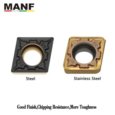
CNMG turning inserts with a medium amount of machining at an unstable condition chipbreaker. These inserts feature a shape that is rhombic 80 degrees with a negative geometry. They come in grades that are appropriate for steel, cast iron, and stainless steel. CNMG turning insert offer a carbide turning solution that is both affordable and efficient for individuals who are working with a limited budget. Turning inserts produced by CNMG have an economy-style negative turning insert. Steel, cast iron, and stainless steel are all appropriate substrates for the CNMG turning insert. CNMG turning inserts offer a carbide turning solution that is economical for individuals who are working with a limited budget.


VNMG Insert
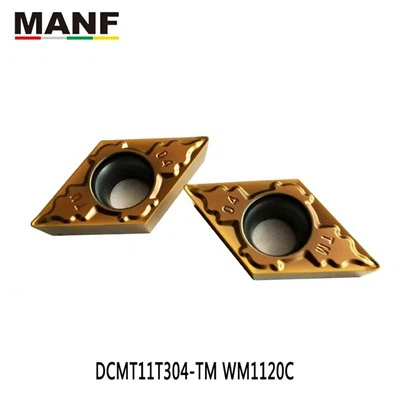
VNMG Insert, used for applications in the semi-finishing and finishing processes. Low forces required for cutting as a result of the edge’s extreme sharpness and the positive rake. VNMG turning inserts have rhombic indexable carbide turning inserts with a 35 degree angle. Double-sided VNMG turning inserts are utilized for a variety of turning-related applications. The VNMG turning insert comes in a variety of radius options, which can be used for finishing, general purpose, and rough turning respectively. Turning inserts from VNMG can give as many as four distinct cutting edges. Inserts in the shape of a “V” provide a pointed shape that is perfect for finishing and semi-finishing.
TNMG Inserts
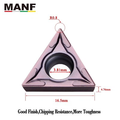
The TNMG turning insert is most commonly used for metal turning, milling, cutting and grooving, thread turning, and other applications that are functionally equivalent. TNMG turning inserts are normally indexable cemented TNMG turning inserts that are replaceable. These inserts are utilised in the machining of nonferrous materials, high temperature alloys, and ferrous materials such as steel and cast iron. TNMG inserts are turning inserts that are ISO standard and are used most regularly in virtually all CNC lathes. Applications in which it is used for Profile Turning and general shaft turning include those in which it is employed. This insert has six different cutting edges..
Material of Turning Inserts
High Carbon Steel
The high percentage of carbon in the composition helps the turning insert to function in conditions of high hardness. However, as the temperature increases, its hardness decreases. But because of this high carbon content, the tools have higher wear resistance and hardness. These are commonly known as tool steel.
High Speed Steel
The high speed steel tools have faster turning speeds. This tool is made of cobalt, tungsten, and chromium-alloyed steel. Due to the presence of strong, harder, and temperature-resistant materials in turning inserts, turning inserts made from these materials can operate under 550∘C to 650∘C
Ceramic Tools
The tools made of ceramic are among the hardest tools used in turning and machining as they can withstand high temperatures. This equipment can function between 1160∘C and 1210∘C. Hence, these are used in finishing operations in the lathe or milling machines.
Cemented Carbide
This tool is an alloy made of tungsten, titanium, and other metals. It gives the tool high strength and hardness. Additionally, due to the presence of carbon, it has higher wear resistance and can withstand higher temperatures. The operating temperature of this tool ranges between 900∘C and 1000∘C.
Diamond
The turning inserts made of diamonds are currently the strongest material. Diamonds are produced naturally on earth. This gives the tool many benefits in terms of temperature resistance, wear resistance, and shock resistance. These implements are utilised to cut tenacious, robust, and hard materials.
Abrasives
There are a variety of abrasive turning inserts, each of which cuts by rapidly rubbing a hard material against the target object. An abrasive material is hard and coarse, and it wears away whatever it is rubbed against. This equipment is embedded with abrasive material. A grinding wheel is one of the simplest types.
Exploring the Role of Turning Inserts in CNC Machining
Turning inserts are a crucial part of CNC machining operations. They are the cutting tools used to create the desired shape, size, and surface finish of a part. Turning inserts come in a variety of shapes, sizes, and materials, and each type has its own advantages and disadvantages. In this article, we will explore the role of turning inserts in CNC machining, and how they affect the quality and efficiency of the machining process.
Turning inserts come in a variety of materials, such as carbide, cobalt, and ceramics. Each type of material provides different levels of cutting performance, as well as wear resistance. The type of material used will depend on the application and the type of part being machined. For example, a carbide insert may be used for a tougher part that requires a higher level of strength and wear resistance. On the other hand, a ceramic insert may be used for a part that requires a smoother finish.
The shape of the turning insert also plays a key role in the machining process. Different shapes are designed for different operations, such as facing, turning, and grooving. Each shape provides advantages and disadvantages, depending on the type of operation being performed. For example, a square insert is ideal for turning applications, while a round insert is better suited for facing operations.
In addition to the shape and material of the turning insert, the cutting edge geometry also affects the quality and efficiency of the machining process. Different cutting edge geometries are designed for different operations, and each geometry has its own advantages and disadvantages. The geometry of the cutting edge must be chosen carefully, as it affects the cutting performance, surface finish, and tool life of the insert.
How to Choose Correct Turning Insert
The geometry of a lathe inserts refers to the shape and angle of its cutting edge, which determines how it interacts with the workpiece and produces chips. The geometry of a lathe inserts can be classified into three types: fine, medium, and rough. Fine geometry is suitable for operations with low cutting depth and feed rate, where low cutting forces and high surface quality are required. Medium geometry is suitable for operations with moderate cutting depth and feed rate, where a balance between edge strength and chip control is needed. Rough geometry is suitable for operations with high cutting depth and feed rate, where high edge strength and chip removal are required.
The grade of a lathe inserts refers to the material and coating of its cutting edge, which determines its wear resistance, toughness, and thermal conductivity. The grade of a lathe bit depends on the type of workpiece material (ISO P, M, K, N, S, H), the type of operation (fine, medium, rough), the machining conditions (good, average, difficult), and the lathe bit geometry. The grade of a lathe inserts should match the properties of the workpiece material and the machining parameters to ensure optimal performance and tool life.
The shape of a lathe inserts refers to the profile of its cutting edge, which determines its clearance angle and accessibility. The shape of a lathe inserts should be chosen according to the requirements of the tool holder and the workpiece geometry.
The size of a lathe inserts refers to the length of its cutting edge (L) and its inscribed circle diameter (IC), which determine its strength and rigidity. The size of a lathe bit should be chosen according to the maximum cutting depth (ap) and the required cutting length (LE) of the operation, as well as the tool holder's clearance angle, the workpiece diameter, and the machine specifications. The size of a lathe bit should be as large as possible to ensure high stability and productivity.
The corner radius of a lathe bit refers to the curvature of its cutting edge at the corner (RE), which affects its edge strength, surface finish, and chip formation. The corner radius of a lathe bit should be chosen according to the machining parameters (ap, fn) and the workpiece material properties. The corner radius of a lathe bit should be as large as possible to ensure high edge strength and durability, but not too large to cause excessive heat generation or chip jamming.
Turning Inserts VS Rapid Feed Insert
A tool that has a cutting part specifically designed for turning is called a turning insert. One of the cutting instruments that is utilised most frequently is known as the turning insert. The portion of the turning insert that generates and processes the chip is known as the working part of the insert. This portion of the turning insert includes the blade edge, the structure that breaks or rolls the chip, the space for chip removal or chip storage, and the passageway for the cutting fluid.
Turning inserts make use of highly developed composite structures, coatings, and geometrical features in order to accomplish both high material removal rates and high levels of precision. Inserts for turning are carbide cutting tips that are used in lathe machines. These tips are held in place by tool holders. These can be utilized for a variety of finishes, including roughing, medium turning, finishing, and facing, depending on the application of turning that is being performed.
A turning insert is the name given to the cutting section of a tool that is specifically developed for use with turning. The turning insert is one of the cutting instruments that is used in a turning operation more frequently than any other. The term “working part of the insert” refers to the section of the turning insert that is responsible for the generation and processing of the chip. This section of the turning insert contains the blade edge, the mechanism that either breaks or rolls the chip, the space for chip removal or chip storage, and the path for the cutting fluid. These inserts can be purchased in a variety of shapes to accommodate the appropriate cutting angle, and they are versatile enough to be used for cutting a variety of materials. On lathes, turning inserts are utilized for the purposes of either cutting or finishing the outer diameter of a workpiece. The production of cylindrical pieces can be accomplished with turning inserts. Machining an exterior surface while the workpiece is rotating or using a cutting tool with a single point is the essence of turning, which may also be described as the process of turning.
The use of fast feed milling inserts makes it possible to machine material up to three times quicker than with traditional methods. The rapid feed insert combines a shallow depth of cut with a high feed rate per tooth, which leads in increased metal removal rates and allows for the production of additional parts. Since the cutting forces are applied to the machine spindle in an axial direction, this results in increased stability as well as a reduction in vibrations, which in turn helps to extend the life of the quick feed insert.
Understanding Turning Insert Holders: Coding and Clamping Methods
Holder Coding
Turning insert holders are coded to indicate various characteristics, such as insert fixation method, insert shape, holder lead angle, and more. The coding system may vary depending on the manufacturer and the standard followed. For example, in a standard coding system, the first character in a holder code represents the insert fixation method. "S" indicates screw clamping, "D" represents rigid clamping, "M" denotes top wedge lock, "P" signifies lever lock, and so on. The choice of insert fixation method depends on factors such as cutting forces, accessibility, and type of machining operation.
Clamping Methods
Turning insert holders use different clamping methods to securely hold the inserts in place during the machining process. Screw clamping, represented by "S" in the holder code, is a common method used for positive inserts, where the clearance angle is not zero. Although it is considered weak in comparison to other methods, screw clamping is compact and provides accessibility, making it suitable for internal or boring machining and operations with lower cutting forces.
Rigid Clamping
Represented by "D" in the holder code, is a stronger method where a pin goes through the insert hole and fixes the insert in place by pushing it downwards. However, it may not be the most suitable method for internal machining or boring due to its bulky nature. Holders used for roughing or operations generating high cutting forces may have shims made from hard material to distribute force and extend the life of the holders. Shims are replaceable components that can be easily replaced if damaged.
Matching Insert Shape and Holder Code
The second character in a holder code represents the insert shape, and it should match the first character of the insert code if you want to use them together. For example, if an insert has a rhombus shape with an angle of 80 degrees, its first code character will be "C". To use this insert with a holder, the holder's second code character should also be "C", matching the insert shape. This ensures that the insert fits properly in the holder and functions effectively during machining.
Holder Lead Angle
The third character in a holder code represents the holder lead angle or approach angle, which is the angle between the cutting edge and the workpiece. Different lead angles are represented by different characters, as per the standard followed. For example, if the lead angle is 93 degrees, it is represented by the character "J" in the holder code.
One of the most common challenges when dealing with turning inserts is wear. Inserts can become worn easily due to the high-speed cutting and contact with the material. To reduce wear, operators should ensure that the cutting edge of the insert is properly sharpened and clean. Additionally, they should use a coolant to reduce heat and friction.
Another challenge is chip buildup. This can occur when chips become stuck in the cutting edge of the insert. To prevent this, operators should use a chipbreaker to break up the chips as they are created. They should also regularly clean the inserts to ensure that no chips become lodged in the cutting edge.
Finally, another common challenge is breakage. This can occur due to the high pressure and temperature that the inserts are exposed to during operation. To reduce the risk of breakage, operators should ensure that the inserts are properly secured in the tool holder and that they are using the correct insert geometry. In addition, they should regularly inspect the inserts for any damage or wear.

The Turning Tools Regrinding Process
Step 1: Send in Your Inserts
We can regrind and downsize inserts from the following materials:
● Carbide
● Ceramic
● Cermet
● PCD
● CBN
● Cerbide
We put all different material inserts through the same sorting process where our engineers will determine if your insert is a candidate for regrinding or downsizing. We are equipped to handle both small and large orders.
Step 2: Provide a Report
Once our engineers have done a thorough evaluation of your inserts, we will provide a detailed report of our findings and recommendations. In this report, we offer pricing information as well as scrap credit options you can use toward your next regrind or insert order.
Step 3: Start Grinding
Once we get your approval of our report, our engineers will work with you to determine the best tool regrind option for your specific application. Our turning tool regrinds are high quality and many times are held to tighter tolerances than new inserts.
We offer a variety of turning tool regrinding services including:
● Periphery Grinding: Grinding around the periphery, or outer edge, of the insert to a specified size and tolerance.
● Thickness/Vertical Surface Grinding: Grinding the face, or thickness, of the insert to a specified size and tolerance.
● Horizontal/Form Grinding: Grinding on the surface to create a high degree of flatness, parallelism, and a superior surface finish.
● Edge Preparation: Reapplying the original hone or land edge of the insert.
Our Factory
Kunshan Meiyaxing Hardware Machinery Co., Ltd. is a company specializing in the production and sales of metal cutting tools. With more than 20 years of experience, we set new technology, high-end machinery and tool manufacturers as one, to provide customers with quality tools, is a direct branch of Hong Kong Meiya International Trading company. Since the establishment of the company - always uphold the "quality", "professional" and "efficient" business philosophy.
